ADD Opcode Walkthrough
To better understand how Opcode components work, let's walk through the implementation of the AddOpcode component.
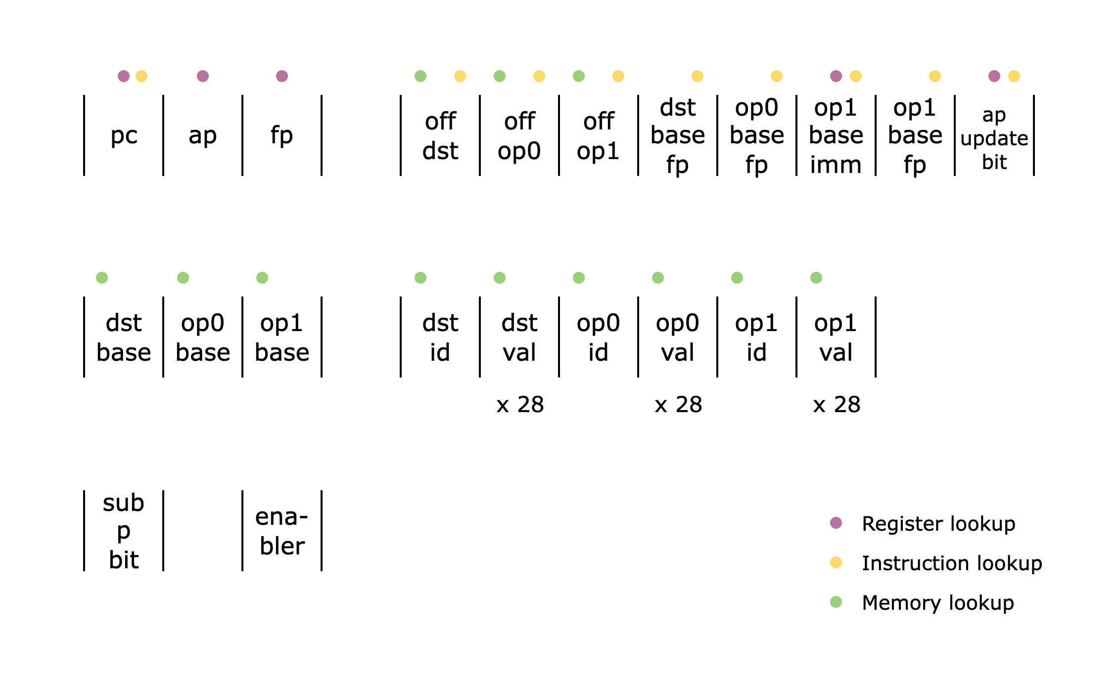
Above is the list of all the columns used in the AddOpcode component. Note that the dst_val, op0_val, and op1_val columns are actually 28 columns each (to support 28 9-bit limbs), but we show them as single columns for brevity.
To reiterate what an Opcode component does from the Main Components section, it verifies the following:
- The offsets and flag values are correct using the
VerifyInstructioncomponent. - The instruction is correctly mapped to the current
Opcodecomponent using the flags. - The operand values
op0,op1, anddstcomputed with the registers and the offsets are correct using theMemorycomponent. - The operation for the current
Opcodecomponent is done correctly. - The state transition of the three registers (
pc,ap,fp) is done correctly using the flags.
An instruction should contain 15 bits of flags but only 5 bits are represented in the AddOpcode columns. Can you see why?
Hint
Hint
Check out how a Cairo instruction is pattern-matched to an ADD opcode here.
Hint
Hint
Check out how the decomposition of the flags is verified here.
Items 1 and 3 should be familiar, as we already covered them in the Main Components section. For item 2, you can check the specs for the ADD opcode here. For item 5, the specs for a valid state transition can be found in Section 4.5 of the Cairo paper.
In this section, we will focus on how item 4 is implemented.
Adding two 252-bit integers
Assuming that the operands op0, op1, and dst are correctly accessed from the Memory table, we now check that the addition of two 252-bit integers is done correctly, i.e. op0 + op1 = dst. As noted in the Felt252 to M31 section, a 252-bit integer is stored as 28 9-bit limbs, so we need to check addition for each of the 28 limbs.
We will incrementally build up to the final constraint.
Limb-wise Addition and Carry
To verify that the two sets of limbs are correctly added, we check limb-wise addition. Since each limb can create a carry, we also add the carry from the previous limb (except for the first limb). Thus, the constraints look like this:
carry_limb_1 = (op0[0] + op1[0] - dst[0]) / 2^9
carry_limb_1 * (carry_limb_1 - 1) = 0

carry_limb_2 = (op0[1] + op1[1] + carry_limb_1 - dst[1]) / 2^9
carry_limb_2 * (carry_limb_2 - 1) = 0

...

op0[27] + op1[27] + carry_limb_27 - dst[27] = 0
We divide op0[0] + op1[0] - dst[0] by 2^9 since this quantity is either 2^9 (if a carry exists) or 0 (if no carry exists). Dividing by 2^9 yields one or zero, respectively. To check that the carry is either 0 or 1, we add the constraint carry_limb_0 * (carry_limb_0 - 1) = 0. For the final limb, we simply check that the addition is correct.
Handling overflow beyond the 252-bit prime field
We also need to account for addition overflowing the 252-bit prime field P (i.e., op0 + op1 = dst + P). To check this, we introduce a witness variable sub_p_bit, a 1-bit value set to 1 if there is an overflow. Note that since P = 2^251 + 17 * 2^192 + 1, we only subtract in the three limbs where P has a non-zero limb: 0, 22, 27.
Now let's revisit the constraints:
sub_p_bit * (sub_p_bit - 1) = 0

carry_limb_1 = (op0[0] + op1[0] - dst[0] - sub_p_bit) / 2^9
carry_limb_1 * (carry_limb_1 - 1) = 0

...

carry_limb_23 = (op0[22] + op1[22] + carry_limb_22 - dst[22] - sub_p_bit * 136) / 2^9
carry_limb_23 * (carry_limb_23 - 1) = 0

...

op0[27] + op1[27] + carry_limb_27 - dst[27] - sub_p_bit * 256 = 0
First, we verify that sub_p_bit is a bit. Then, we subtract sub_p_bit from the first limb, sub_p_bit * 136 from the 22nd limb, and sub_p_bit * 256 from the 27th limb. (Note that 136 and 256 are the values of P in the 22nd and 27th limbs, respectively.)
A caveat of this approach is that subtracting sub_p_bit can introduce an underflow, i.e., (op0[0] + op1[0] - dst[0] - sub_p_bit) / 2^9 = -1. This means that carry_limb_0 can be -1 as well as 0 or 1. Thus, we update the constraint for all carries to the following:
...

carry_limb_1 * (carry_limb_1 - 1) * (carry_limb_1 + 1) = 0

...
Optimization
To optimize the number of constraints, we can combine all the constraints for each limb into a single constraint. Naively checking that carry_limb_1 = (op0[0] + op1[0] - dst[0] - sub_p_bit) / 2^9 would require a dedicated column for carry_limb_1. Instead, we keep carry_limb_1 as an intermediate value and inline the equation when computing the next carry. For example, the second-limb carry is computed as follows:
carry_limb_2 = (op0[1] + op1[1] + ((op0[0] + op1[0] - dst[0] - sub_p_bit) / 2^9) - dst[1]) / 2^9
This way, we avoid allocating extra columns for the carries and proceed until the last limb, where we check that the giant equation is correct.
This is possible because the computation does not involve any multiplication of witness values, so the constraint degree does not blow up.
Final constraint
One last note: in the implementation, we replace division by 2^9 with multiplication by 2^22, which is equivalent in the M31 field since 2^9 and 2^22 are multiplicative inverses—i.e., 2^9 * 2^22 = 1 mod 2^31 - 1.
So the final constraint looks like this:
sub_p_bit * (sub_p_bit - 1) = 0

carry_limb_1 = (op0[0] + op1[0] - dst[0] - sub_p_bit) * 2^22 // intermediate representation
carry_limb_1 * (carry_limb_1 - 1) * (carry_limb_1 + 1) = 0

...

carry_limb_27 = (op0[26] + op1[26] + carry_limb_26 - dst[26]) * 2^22 // intermediate representation
carry_limb_27 * (carry_limb_27 - 1) * (carry_limb_27 + 1) = 0

op0[27] + op1[27] + carry_limb_27 - dst[27] - sub_p_bit * 256 = 0
Enabler column
Finally, we introduce the last column in the AddOpcode component: the enabler column. As the name suggests, this column enables or disables the constraint for the current row. It is used to support the dummy rows added to the end of the table to make the number of rows a power of two. In other words, it is set to 1 for all valid ADD opcode calls and 0 for all dummy rows.