Main Components
Now that we have a basic understanding of Cairo and the building blocks that are used to build the Cairo AIR, let's take a look at the main components of the Cairo AIR.
For readers who are unfamiliar with the concepts of components and lookups, we suggest going over the Components section of the book.
Fetch, Decode, Execute
Cairo follows the common CPU architecture of fetching, decoding, and executing an instruction in a single CPU step. Below is a high-level diagram of what a single CPU step looks like in Cairo.
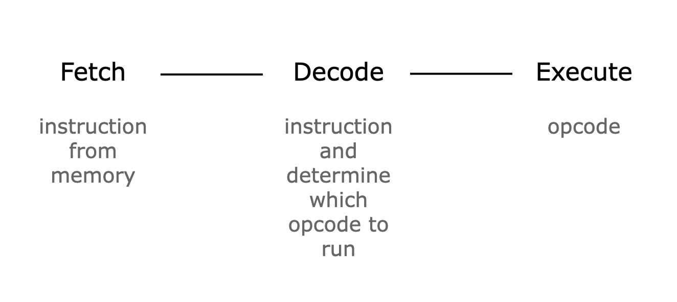
Since we need to prove the correctness of all CPU steps, the Cairo AIR writes the results of fetching, decoding, and executing an instruction at every CPU step into a trace and proves that the constraints over the trace are satisfied—i.e., consistent with the semantics of Cairo.
Let's keep this in mind while we go over the main components of the Cairo AIR.
1. Memory Component
The first component we need is a Memory component, which implements the non-deterministic read-only memory model of Cairo.
In Cairo AIR, instead of mapping the memory address to a value directly, we first map the address to an id and then map the id to a value. This is done to classify the memory values into two groups: Small and Big, where Small values are 72-bit integers and Big values are 252-bit integers. As many memory values do not exceed the Small size, this allows us to save cost on unnecessary padding.
As a result, the Memory component is actually 2 components: MemoryAddressToId and MemoryIdToValue.
The constraints for the MemoryAddressToId and MemoryIdToValue components are as follows:
- An
addressmust appear once and only once in theMemoryAddressToIdcomponent. - An
idmust appear once and only once in theMemoryIdToValuecomponent. - Each
(address, id, value)tuple must be unique.
The first constraint is implemented by using a preprocessed column that contains the sequence of numbers [0, MAX_ADDRESS) and using this as the address values (in the actual code, the memory address starts at 1, so we need to add 1 to the sequence column).
The second constraint is guaranteed because the address value is always unique.
A short explainer on how the id value is computed:
The id value is a 31-bit integer that is incremented by 1 from 0 whenever there is a unique memory access. For example, if the addresses [5, 1523, 142] were accessed in that order, the ids for those addresses will be (5, 0), (1523, 1), and (142, 2).
Since an id value needs to include information as to whether the corresponding value is Small or Big, we use the MSB as a flag (0 for Small and 1 for Big). Thus, an id value that corresponds to a Small value can occupy the space [0, 2^30), while an id value that corresponds to a Big value can occupy the space [2^30, 2^31).
In reality, the size of each table will be [0, NUM_SMALL_VALUES_ACCESSED) and [2^30, 2^30 + NUM_BIG_VALUES_ACCESSED), where NUM_SMALL_VALUES_ACCESSED and NUM_BIG_VALUES_ACCESSED are values that are provided by the prover. To make sure that the id values are created correctly, we can use the preprocessed column as the id values.
2. VerifyInstruction Component
The VerifyInstruction component is responsible for accessing the instruction from the Memory component and decomposing the retrieved value. As mentioned in the Felt252 to M31 section, a 252-bit integer is stored as 28 9-bit limbs, so we need to decompose the limbs and concatenate them to get the values we need. For example, as in Figure 2 in order to get the 3 16-bit offset values, we need to decompose the first 6 limbs into [9, [7, 2], [9], [5, 4], [9], [3, 6]] and concatenate them as the following: [[9, 7], [2, 9, 5], [4, 9, 3]]. Then, the remaining 6-bit value and the next limb will correspond to the 15-bit flags, and the next (8th) limb will be the opcode extension value. The other 20 limbs should all be zeros. At the end, we will have decomposed the instruction value into 3 16-bit offsets, 2 chunks of flags, and a 9-bit opcode extension.
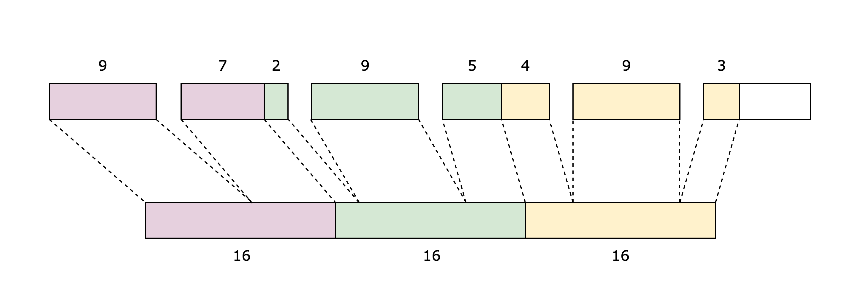
Note that the decomposition will be constrained by range checking that each integer is within its corresponding range.
3. Opcode Component
Since every Cairo instruction can be mapped to a specific Opcode, we can check that a Cairo instruction is executed by checking that the corresponding Opcode component was executed correctly. You can think of the Opcode component as the main component that uses the VerifyInstruction and Memory components.
We define a single Opcode component for each predefined opcode and a GenericOpcode component, which is used for all instructions that do not map to any of the predefined opcodes.
The following is a list of constraints that the Opcode component needs to verify:
- The offsets and flag values are correct using the
VerifyInstructioncomponent. - The instruction is correctly mapped to the current
Opcodecomponent using the flags. - The operand values
op0,op1, anddstcomputed with the registers and the offsets are correct using theMemorycomponent. - The operation for the current
Opcodecomponent is done correctly. - The state transition of the three registers (
pc,ap,fp) is done correctly using the flags.
Of these constraints, items 2 and 4 are self-contained—meaning they do not require any other components to be verified. We will explore how the remaining three are verified using lookups between the different components.
Bringing It All Together
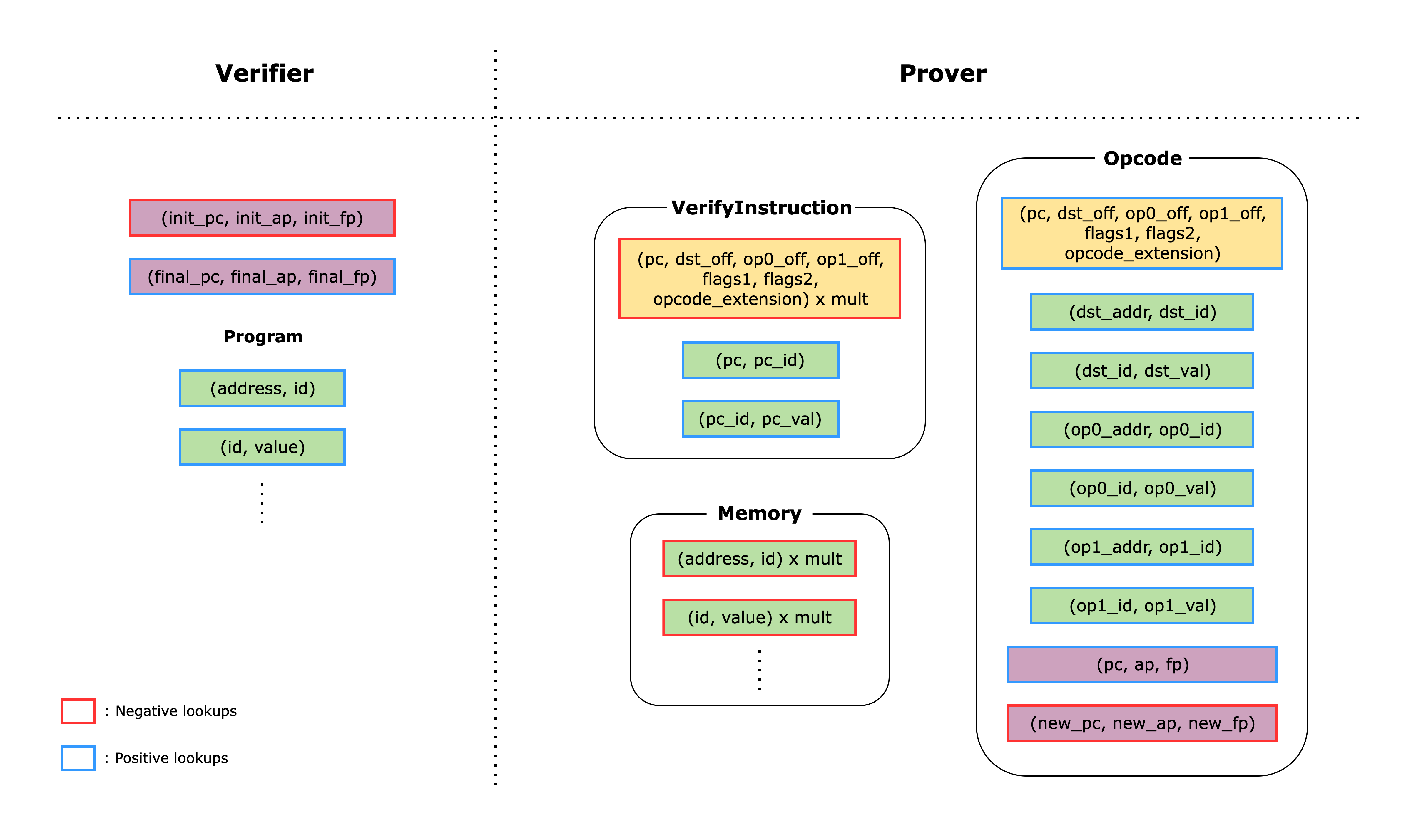
The following figure shows how each of the main components are connected to each other using lookups.
If we look at the right-hand side first, we can see the main components of the Cairo AIR. The boxes in each component correspond to lookups within that component, and boxes with the same fill color correspond to lookups of the same values. Some lookups are yielded (i.e., subtracted), while others are used (i.e., added). Yielded lookups have red edges; used lookups have blue edges.
On the left-hand side, we can see lookups that are computed directly by the verifier from data provided by the prover as part of the proof.
Each component has a claimed sum value that corresponds to the sum of all the lookups in the component. These claimed sums are provided by the prover as part of the proof, and the verifier adds them together along with the lookups on the left-hand side. If the total sum is zero, the verifier is convinced that the proof is valid.
Memory Lookups
The memory lookups correspond to looking up the (address, id) and (id, value) pairs. In the Memory component, each of the lookups is multiplied by a witness value mult, which indicates the number of times each memory address was accessed. Since the memory accesses are added to the total sum and the same amount is subtracted from the total sum in the Memory component, the total sum for memory lookups should equal zero.
Note that the verifier also adds lookups for the Cairo program, which is necessary to ensure that the correct program is actually stored in memory and is properly executed.
Instruction Lookups
Once the VerifyInstruction component retrieves the instruction value using the (pc_addr, pc_id) and (pc_id, pc_val) lookups, it subtracts the lookup of the tuple (pc, dst_off, op0_off, op1_off, flags1, flags2, opcode_extension), which are the decomposed values of the instruction. This lookup also has a mult witness because the VerifyInstruction component has a single row for each unique pc value (i.e., the Cairo instruction stored at the pc address). Thus, the same pc value can be invoked multiple times throughout the program, and the mult value represents the number of times the same pc value is invoked.
Since the same tuple lookup is added to the total sum whenever the Opcode component uses the same instruction, the total sum for instruction lookups should equal zero.
Register Lookups
After computing over the operands, a Cairo instruction updates the register values based on the values in the flags. In an Opcode component, this update logic is verified using the columns pc, ap, fp, new_pc, new_ap, new_fp, and by constraining the values with the flags.
In addition to checking that each state transition is done correctly, we also need to make sure that the initial register values (i.e., before running the program) and the final register values (i.e., after running the program) satisfy the Cairo semantics. For example, the final pc must point to an instruction that runs the JUMPREL 0 opcode, which is an infinite loop (you can check the rest of the semantics enforced here).
Once we have verified that the initial and final register values are correct and each state transition is done correctly, we do a final check that the register values are all connected—that is, the register values used by the second instruction are the same as the new register values of the first instruction, and so on. We check this by adding the lookup of the (pc, ap, fp) tuple and subtracting the lookup of the (new_pc, new_ap, new_fp) tuple for each Opcode row. When we add up all the lookups, the total sum for register lookups should equal (init_pc, init_ap, init_fp) - (final_pc, final_ap, final_fp). Thus, the verifier can compute the lookups of the initial and final register values, subtract the first, add the second, and check that the total sum is zero.